Build your own Light sensor [LDR + Homeyduino – English version]
![Build your own Light sensor [LDR + Homeyduino – English version]](https://huisvanvandaag.nl/wp-content/uploads/2018/10/LDR-sensor.jpg)
A light sensor measures the amount of light in a certain room and by linking this to Homey, the sensor can control devices or ‘flows’. In this way you can automatically switch on your lights when it gets (too) dark or vice versa, switch off your outdoor lighting when the sun rises.
After we finally managed to make a WiFi (water) thermometer for the pond last week, and have it communicate with Homey by means of copy-pasting code on an Arduino/ESP8266 until it work, I got a real taste for it. This time I checked another sensor off the wish list: the light sensor (LDR).
By using these sensors you can easily save electricity, because your lamps do not switch on unnecessarily when it is still light enough outside, and, if desired, switch off automatically when it becomes light enough again. On the other hand, it is user-friendly because on cloudy or otherwise dark days the lights will come on a little earlier, you won’t get this result with time based lighting flows.
Turnkey solution
Of course there are many ready-made solutions for this, but these are often battery powered and since the battery consumption here is already disproportionate, I prefer to have as many sensors as possible connected to a socket.
DIY light sensor (LDR)
That is why as a hobbyist I have opted for the DIY alternative, namely with an LDR, Light Dependent Resistor sensor, or a light sensitive sensor. It’s also a nice project to learn how thses sensors works, and it will work with either your Homey Pro or your Homey Bridge.
The advantage of Arduino/ESP8266 is that it can easily be linked to Homey Pro or you Homey Bridge since the release of Homeyduino. This still requires some puzzling on my part, because as indicated I have little to no knowledge of programming. However, with the interest in learning something, combined with a healthy drive to keep going, you will come a long way. You can also use your DIY sensors as a trigger for your flows.
The necessities:
- Microcontroller with WiFi and 5V: D1 Mini NodeMcu
- Micro USB Charger
- LDR Sensor or ready-made LDR sensor with resistor and potentiometer
- breadboard
- Resistance
- Homey Smart Home HUB or Homey Bridge with Homeyduino app installed
Also necessary, but only to be configured once, a computer or laptop with installed:
Connection diagram
Follow the diagram below to connect the sensor to your board. The image below shows an Arduino Uno but connecting it to an ESP8266 NodeMCU or D1 Mini is almost the same, voltage also works at 3.3V.


Code
Below is the code, just like the WiFi Water Thermometer, itself compiled from code already available for Arduino and Homeyduino. It works properly, but since I, as a layman, have little or no experience with coding myself, this can most probably be done more efficiently.
If you do have this knowledge and have suggestions, please let me know! Uploading is done via Arduino IDE, if you are not familiar with this, read here for an extensive manual . Make sure you have selected the correct board in settings in Arduino IDE and that you upload the code at 9600 baud. If your ESP8266 board doesn’t work, you can try flashing it first with the NodeMcu Flasher.
// Code for Homeyduino made by Smart Home Blog https://huisvanvandaag.nl.
// Take a look at my site for more Homeyduino and other Smart Home projects.


#include <ESP8266WiFi.h>
#include <WiFiClient.h>
#include <Homey.h>

int LDRsensor = A0;
// Configure the LDRsensor pin, in this case we
// will connect it to the analog port A0 of the arduino: A0

void wifi() {
  if (WiFi.status() != WL_CONNECTED) {
    WiFi.begin("<SSID>", "<PASSWORD>");
    uint8_t timeout = 30;
    while (WiFi.status() != WL_CONNECTED) {
      delay(500);
      Serial.print(".");
      if (timeout<1) break;
    }
    if (WiFi.status() == WL_CONNECTED) {
      //Print IP address
      Serial.print("Verbonden met WiFi! (");
      Serial.print(WiFi.localIP());
      Serial.println(")");
    }
  }
}

void setup() {
  Serial.begin(9600); // put serial port to 9600 baud.
  Homey.begin("SENSOR NAME");
  Homey.setClass("sensor");
  Homey.addCapability("measure_luminance");
}

// this loop will run constantly
void loop() {
  // print LDR waarde via seriele monitor
   wifi();
  Homey.loop();
 // Serial.print("LDR waarde: ");
  Serial.print(analogRead( LDRsensor));
  Serial.println("");
  Homey.setCapabilityValue("measure_luminance", analogRead( LDRsensor));
  delay(1000); // wait 1 minut=  60000 ms
}
Testing the board
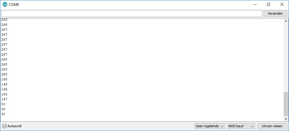
Now that you have successfully uploaded the code to the Arduino board, we will have to test it. We do this by opening the Serial Monitor in Arduino IDE, click on Tools and then Serial Monitor or use the keyboard shortcut CTRL+SHIFT+M.
A new screen will then open on which you can read the values coming from the sensor. Values can vary anywhere between 0 and 999. With 0 being the extreme state of darkness and 999 being a very well lit space. The choice of resistor you use may affect the measured data. In the image below I tested the sensor outside on a partly cloudy day, in my opinion the measured amount of light should therefore be higher. This has little influence on the use of the sensor itself, except that an accurate sensor can also switch more accurately.
Finishing and Protection
We’ve put the sensor in a somewhat neat box, so that everything is just a bit moreprotected and it also looks less messy. On mywish list still is a 3D printer, so that any cases can be custom made. But as long as it isn’t there yet, we’ll solve it differently. As you could already see with the WiFi water thermometer, I then used a simple plastic box from the construction market. This actually worked out fine, so we’re using it again for this project.


Conclusion
This way you can build a well-functioning light sensor with limited resources. Some of the problems I encountered initially had to do with setting up the flows. This pays very close attention and sometimes you create a flow that is interpreted differently by Homey than you had invisioned. But this is solved simply by trial and eroor.
Depending on the accuracy of the sensor, you have to determine for yourself at what light intensity you want your lamps to be activated. You also need to have the flow active at set times, but not 24 hours a day. You obviously don’t want your lights to turn on in the middle of the night. All in all, this is a process that requires some attention, but once you have it working properly, you don’t have to worry about it anymore.
The next step: Multi Sensor Homeyduino
Simple sensors are often enough, but sometimes it’s just useful to have multiple sensors in one. For example, you can create more complex triggers by combining a light sensor with a motion sensor. This will be the next project, at the moment various sensors have been ordered and are on their way.
The sensors are now in, built and tested. You can read about it here!
![Build your own Wifi operated water thermometer [Homeyduino – English version]](https://huisvanvandaag.nl/wp-content/uploads/2018/08/Vijver-1.jpg)
![Build your own CO2 sensor with Homeyduino [English version]](https://huisvanvandaag.nl/wp-content/uploads/2021/01/Homeyduino-Co2-sensor-800x450.jpg)
![Homeyduino multi sensor: Co2-LDR-DHT11 [English version]](https://huisvanvandaag.nl/wp-content/uploads/2021/01/Multi-sensor-Homeyduino-Co2-LDR-DHT11--800x450.jpg)
![Build your own Clapper like switch [Homeyduino English version]](https://huisvanvandaag.nl/wp-content/uploads/2019/05/Clapper-Switch-Homeyduino.jpg)
